How much heat do LSC products produce (BTU output)
I need a new fixture template for a console. Where do I go.
We supply fixture templates for Clarity, maXim and Mantra Lite consoles, free of charge. All we ask is that you fill in a webform request and include the full users manual or DMX chart. Requests without this information attached, or with just a generic website address will not be actioned.
maXim
Please check to see if the template is already available via this link.
If the template is not on the list, click here to request a custom template.
Mantra Lite
Please download and install the latest library via this link.
If the fixture you require is not in the library, click here to request a custom template.
Clarity
We are no longer able to create new fixture templates for Clarity.
There is a powerful fixture Editor in Clarity that allows the user to create their own templates.
Detailed instructions are in the User Manual, or via this link. Fixture Editor Guide
Template requests take 10-15 business days to process.
All Products Latest software releases for all current LSC products
All Products Made In Australia certification
All Products How do I PAT test a 3phase device
Many testers do not have a lot of experience testing 3phase electronic devices. These notes will assist them to understand how to do the tests in accordance with the local regulations.
Click here to download the PAT testing guide for 3phase products
All Products LSC Desklamp XLR wiring
The wiring of the LSC desklamps is outlined below.
This wiring is the same for all LSC products from the original Precept12 to the latest LX Clarity consoles.
Pin 1 -> Do not use
Pin 2 -> 0v
Pin 3 -> +12v DC
N.B. This wiring is different to many brands of desklamps, including Lil'lights. Connecting a desklamp that is wired differently will almost certainly cause the console to shut down, possibly losing show data, and may even damage the console.
APS/Powerpoint Neutrik powerCON True1 Safety Notice
Neutrik have issued a Product Safety Notice for the powerCON True1 connector. LSC no longer use this connector, but some product was shipped using the True1 before the notice was issued. If you own or use any product with this connector then please read this document. |
Clarity Runs in Demo mode only (HASP driver not installed)
If Clarity runs in Demo Mode and you have a license dongle (Purple HASP USB key) connected, then the HASP drivers are not installed.
Mac.
Click here to download the latest HASP driver for OSX ???
After the file has downloaded, open the Sentinel_Runtime DMG image, run the installer and follow the prompts.
Windows
Click here to download the latest HASP driver for Windows 10/11.
After the file has downloaded, unzip the Sentinel_LDK_Run-time_setup+(Win10_11).zip file, run the installer and follow the prompts.
Clarity What versions of Windows and Mac OSX are compatible
Development of the Clarity software ceased in mid 2020.
The supported operating systems at that time were
- Windows 10 (v20H2)
- Mac OSX Catalina
These are the last official versions of operating systems that are supported by Clarity.
Clarity may work on future updates of Mac OSX and Windows but they will not be officially supported.
Update March 2022.
Clarity has been tested on
- Mac OSX Monterey (v12.3)
- WIndows 11 (v21H2)
N.B. Clarity will NOT work on computers with ARM processors. This includes the new Mac M1 computers and the some Microsoft Surface computers.
The first problem is that the 3rd party Sentinel HASP dongles used by Clarity are not compatible with Arm processors, which means Clarity will only ever run in demo mode.
Additionally the VX/QX wing drivers are not compatible with Arm processors.
Clarity Clarity crashes with BSOD (Blue Screen of Death) after Windows10 (May 2020 v2004) update installed.
Due to changes introduced by Microsoft in the May 2020 Windows10 (v2004) update, the Clarity software crashes with a BSOD (Blue Screen of Death) when run in licensed mode.
The issue is caused by the 3rd party Sentinel HASP driver that Clarity uses for piracy protection.
The problem is easily solved by installing the latest HASP driver update.
Click here to download the HASP 8.11 Installer for Windows
If the computer will not boot to allow you to install the update, please refer to this article
https://supportportal.gemalto.com/csm?id=kb_article_view&sys_kb_id=39f264ea1b981854f12064606e4bcb2f
Clarity Using Clarity for Windows on high DPI displays
Clarity is designed to work on almost any Windows or Mac computer, including those with high DPI screens (a very high resolution screen in comparison to the physical size (e,g, Microsoft Surface PC, 13" laptops with 4k screens. Mac Retina screens).
However the default settings that Windows uses conflict with the settings in Clarity, resulting in the software appearing very small on the screen, with all the buttons, toolbars and text being randomly scrambled.
TechNote CT-N01N explains how to change the default Windows High DPI settings to work with Clarity.
Clarity VX wing not recognised on Windows 10
Some newer Windows 10 computer do not recognise the VX wing when connected. On other computers the VX wing is recognised by Clarity, but not by the VX/QX UpdaterTool software.
The issue is that a security setting has blocked the automatic driver installation process. It can also occur if the user accidentally clicked 'Do not trust' to the question about installing LSC drivers when first installing Clarity.
The solution is to manually install the driver by following these steps.
1) Open Device Manager. (Right click on the start icon and it appears in the pop-up menu.
2) With the VX connected look for the item called COM + LPT ports and expand it.
3) There will be an item called LSC VX10, LSC VX20 , LSC QX1, USB Serial, or Unknown in the list. Click and select it.
4) Look for the Update Driver button and click it.
5) Select the option to Browse to the driver location.
6) Navigate to C:Program Files (x86)\LSC\Clarity\Drivers and press OK.
The driver will now install and should appear correctly in Device Manager. Both Clarity and the VX/QX UpdaterTool should now work.
Clarity VX wing issues with USB3.0 ports (Windows only)
This FAQ is for users having issues with VX wings dropping out or responding slowly to button presses when connected to a USB3.0 port on a Windows PC, but work perfectly when connected to a USB2.0 port on the same computer.
The problem is caused by the USB3.0 drivers for your computers USB chipset (hardware). To resolve the problem visit your computer manufacturer's website and search for the driver downloads section. Install the latest USB3.0 chipset drivers and the VX wing should start working reliably.
DMX XLR5 to RJ45 wiring diagram
Here are the details of the ANSI E1.11 standard wiring for DMX using both XLR5 and RJ45 connectors.
DMX Can I use Cat5/Cat6 cable for DMX?
One of the most common cables found these days in buildings is the humble Cat5 cable.
It's use in computer networks means that it has had found wide appeal, to the point where the average electrician is comfortable in using it and terminating it.
Due to its common use, questions are often asked about running other types of signals over this type of cable. Naturally enough the question of running DMX512 over Cat5 has also been asked.
ESTA, a suppliers association in the US (LSC is a member) many years ago took on the responsibilty of overseeing the development of standards for our industry. When this question was raised some 10 years ago, a Task Group was formed to do practical testing on DMX512 signals over Cat5 cable to see what the results would be.
The Task Group's mission was to employ an independent laboratory to carry out a series of comparison tests between a typical cable presently used for hardwired DMX512 installations, and conventional Category 5 data cable. The goal of this testing was to establish whether Category 5 cable could be used as a low cost substitute in permanently wired DMX512 installations. Two series of lab tests were conducted in July and November of 1998 at MPB Technologies in Airdrie, Alberta. Additional tests were conducted in December of 1999.
Data obtained from all three of these test sessions confirms that, in most respects,
UTP and STP Category 5 cable can be expected to perform at least as well as EIA-485 rated data cable for DMX512 applications.
For the technically minded, a summary of the three reports is available on the ESTA website here (PDF, 15kB). It describes the tests and gives general conclusions.
Part 1 of the report (PDF, 1.07MB) gives the details of the first series of tests that compared the DMX512 handling characteristics of a typical EIA-422 rated data cable with those of a standard Category 5 unshielded twisted pair (UTP) cable. Radiated emissions tests were also done. Results of these tests indicated that Category 5 UTP cable performed as well as conventional DMX512 cable.
Part 2 of the report (PDF, 429kB) details the second series of tests that were carried out with Category 5 shielded twisted pair (STP) cable, and also included radiated and induced signal immunity tests to current IEC standards on all cable types.
Part 3 of this report (PDF, 390kB) details the third series of tests that were conducted to determine the effect of combining different types of cable (i.e., Category 5 and EIA-485) on the same wire run. At this time, tests were also done with Rosco/ET IPS equipment to determine whether the use of Category 5 cable caused any timing problems with the talkback data.
The Technical Standards Committee of ESTA has in recent years produced an ANSI standard for DMX512 wiring including over Cat5 cables.
The standard is known as ANSI E1.27-1 - 2006 and its title is
Entertainment Technology-Standard for Portable Control Cables for Use with USITT DMX512/1990 and E1.11 (DMX512-A) Products.
A copy of this standard can be purchased from ESTA's online website.
DMX Why does my DMX do strange things sometimes?
There is one simple rule, 99% of ALL DMX problems are caused by cabling issues. This can be anything from using the wrong type of cable, to incorrect earthing, lack of termination, or using Y-splits. Any or all of these can cause DMX to do strange things.
Unfortunately the results of such cabling errors do not always show up straight away. It may be 12 months later when the connectors start to corrode, or when they install a Cell phone tower just up the road. Also in touring systems it may work for the first 5 shows, then on the sixth night it stops working, only to work again on the next night.
So how do solve these problems?
1) Are you using RS-485 computer data cable?
This is VERY important.
You CANNOT use microphone cable !
Sure it will work most of the time, but sometimes you will get flickering of lights, or random movements of mirrors, etc. Many users first discover this problem when upgrading to an LSC console, and therefore wrongly blame the new console. The problem is that the LSC consoles update the DMX at the maximum refresh rate (as defined in the DMX1990 standard). This is to ensure the fastest response from the lighting rig. However it also shows up bad cabling, that may have worked with a slower console, but does not work with full speed DMX.
2) Do you have a DMX terminator installed?
Once again this is VERY important. The system may work without a terminator, but it will not be reliable. The terminator stops data reflections, which can cause standing waves in the line, often stopping one light in the middle of the cable from working, whilst those on either side work perfectly. Sometimes replacing a cable in the system will move the fault to another light, seemingly at random.
To make a DMX terminator simply solder a 120R resistor across pins 2 & 3 of the XLR connector.
3) Remove any Y-split leads.
If you want to split your DMX cabling into 2 separate runs (eg front and rear truss) then use a DMX splitter (such as the LSC Delta units shown). If you try to use a Y-split lead (2 leads into one plug) then it will not work.
As with all things DMX the Y-lead may work sometimes, but you can be sure that it will cause problems when you least expect them.
4) Check your earthing.
Always connect the earthing shield of the cable to the Pin 1 of the XLR plug.
NEVER connect the body of the XLR plug to the earth of the cable.
Otherwise you will usually get problems connecting different brands of equipment or connecting equipment with different power sources.
The above 4 items highlight the biggest problem with DMX. It will very often work with incorrect cabling. This makes us all a little lazy, so we start to take shortcuts with our cables and then cannot work out what is wrong when something does actually go wrong.
In the last 30 days I have fixed 5 systems with strange DMX problems. ALL OF THEM were due to bad cabling. One client had been using the wrong cable type and no terminators for 3 years without any problems, and then suddenly in one venue nothing worked properly. As they had gone so long without any problems they were convinced that it could not be cabling, but after replacing the cables and installing terminators the system worked perfectly. They have since noticed a lack of flicker, something that they had assumed was faulty dimmers for the last 3 years........
So next time you have ANY sort of DMX problem start at the basics and check ALL the cabling in the venue, both installed and portable. We recently solved a random flickering problem at a venue where we knew the cabling was correct. As part of the fault finding we discovered that one of the patch leads, connecting two of the dimmer racks, had been repaired. The repair company did not understand DMX and so had used a normal shielded audio cable. One small 30cm cable, a tiny part of the 800m of total cabling was the cause of the problem.
maXim Why doesn't my maXim console recognise my USB stick
The USB hardware on the maXim was designed over 10 years ago, when USB sticks were 2MB or 4MB (yes, MB not GB!). This means that many new USB sticks do not work in the maXim.
To resolve this problem the USB stick needs to be reformatted on a Windows computer. (Warning: this will destroy all the data on the USB stick.)
There are two settings that are critical: the Quick Format option must be turned off and the Allocation Unit Size must be set to the smallest possible option. See the image below for details.
Note: this full format will take at least 15 minutes. If the format takes less than one minute then the Quick Format was not disabled and the USB stick will not work with the maXim.

PTFD Dimming What is PTFD dimming and why you need it.
This article is dedicated to explaining the term ‘Pulse Tranformer Fired Dimmer' (hereafter refered to as PTFD). This is a tried and proven piece of technology that has been almost completely replaced by modern semiconductor circuitry. Unfortunately as you will find out, the change is not neccessarliy for the better.
It is also one of the major reasons that the LSC GEN VI, FilmPRO, UNITOUR, UNITY, TRS, TEKO, EKO, e24, ePRO, iPRO & TDS dimmers are so popular and well liked by lighting crews all over the world.
What is PTFD?
Back in the dim, dark past (sorry for the bad pun) lighting dimmers used a small ‘pulse transformer' to control the power device, usually a triac or an SCR. (We will use the generic term ‘triac' throughout this document to keep things simple). The ‘triac' is the part of the dimmer that actually controls the voltage coming out of the dimmer to the lights.
A 12 channel dimmer needed 12 transformers, one per channel. The transformer was used to provide isolation between the high voltage (100-240v) mains output and the low voltage (~12v) of the dimmer electronics. A pulsed signal was fed into the input of the transformer, and the output was connected to the input of the ‘triac'.
The result was a dimmer that could control virtually any type of connected load. This included inductive loads (eg. Anything with a transformer in it, such as pinspots, 12v EVL dichroic lamp systems, etc) and reactive loads (discharge lamps and fluorescent lamps).
Then in the 1980's a new integrated circuit device became available known as an "opto-isolator" (also known as; opto-coupler, MOC). This device uses an LED and a photo-transistor to provide the same level of high-low voltage isolation as a pulse transformer, at a FAR LOWER COST.
Due to the lower cost, and the fact that a chip (Integrated Circuit) is easier to work with than a transformer in manufacturing, the vast majority of dimmer manufacturers switched to this great new device.
So what is the problem with an opto-isolated dimmer?
As always in life, you don't get anything for free. The opto-isolators have one major disadvantage.
They do NOT provide power to drive the ‘triac' !
Instead the dimmer circuitry uses the connected load to provide the power, so;
The opto-isolated dimmer's performance is dependent on the load connected to it.
In the case of a simple high power load (eg a 1000w Par64) this is not usually a problem. The circuitry actually works quite well.
In this scenario the LSC RED3 and Redback range of dimmers are an ideal choice.
The problems occur when you get into any of the following situations.
| Very low power circuits (eg. a 15w festoon lamp) | ||
| Inductive loads, such as; | ||
| Pinspots |  | |
| ELV 12v dichroic lamp systems |  | |
| Transformers such as gobo rotator power supplies |  | |
| Motors, such as mirror ball rotators |  | |
| Motorised Disco Effects (these often contain a motor and a transformer) |  | |
Reactive loads such as Intelligent lights, Discharge lamps and Fluorescent lamps |  |
If the load is very small (eg 15w) there is just not enough power to fire ‘triac'. The result is that most opto-isolated dimmers require a minimum load of 100w in order to work.
If the load is inductive or reactive then there is a problem with the voltage and current getting out of phase with each other (due to the laws of physics) which can cause a false trigger of the ‘triac', which causes the lights to flicker or flash.
If the load is both of the above (eg. a small transformer driving a gobo rotator or a 35w dichroic) then some opto-isolated dimmers will simply never turn off the ‘triac', so your light or gobo rotator keeps working at full power, even with the dimmer control at zero !
A PTFD dimmer rack does NOT have any of these problems.
It simply dims the light as the operation of the ‘triac' is completely independent of the load !
Customers usually learn this critical piece information too late.
In many instances the first the customers knows of this "compromise" is after a new dimmer installation is finished.
They decided to ‘upgrade' their 20 year old analogue dimmers that were transformer fired, to new digital opto-isolated dimmers. However once installed the new dimmers DON'T WORK AS WELL AS THE OLD ONES, due to the issues outlined above. So having spent many 1,000's of dollars they are actually worse off than before !
The solution to this dilemma is to make sure that the end user FULLY understands the difference between a Pulse Transformer Fired dimmer and an Opto-isolated dimmer BEFORE THEY MAKE THE PURCHASE !
Only a Pulse Transformer Fired dimmer offers the superior performance.
So how do I tell the difference?
Here is a photo of an LSC ePRO dimmer firing card.
You can see 4 large black ‘cubes' on the PCB, these are the pulse transformers.

- GEN VI
- FilmPro
- UNITOUR
- UNITY
- EKO
- TEKO
Here is a photo of an opto-isolated dimmer firing card. You can clearly see the white 6-pin IC device. The labelling says it is a MOC3052. Various manufacturers use slightly different devices, but they will usually be a 6pin Dual InLine (DIL) IC package.

The following LSC dimmers are all Opto Fired:
- Redback
- RED3
Hard Firing
Some manufacturers try to get around this with what is called Hard Firing. This involves sending a string of small pulses to the opto-isolator (just like we do with our PTFD's), so that if/when the ‘triac' misfires, or turns off from a lack of power, it will automatically re-trigger.
Whilst this can help the situation it is a bit like trying to cure cancer with a band-aid. The solution only helps hide the problem, the dimmer still cannot control certain loads.
Some sales jargon will try to convince the end user that Hard Firing solves all the problems with opto-isolation. It does not !
The Proof
The best way to prove this to a customer is to demonstrate the problem. LSC staff carry a Pinspot, a 12v desk lamp with transformer and a mirror ball motor with them when they do demonstrations. The LSC PTFD dimmers can control all of these devices without any problem.
Almost all opto-isolated dimmers fail this demonstration completely. The mirror ball motor does not start, or if it does it never stops. The Pinspot flickers at low levels and the 12v desk light cannot be dimmed, it simply stays on at full brightness as the dimmer channel is dimmed up and down.
The Cost
LSC Pulse Transformer Fired dimmers are more expensive than opto-isolated dimmers. However a 5 tonne truck is also more expensive than a family car. You would never consider trying to carry 5 tonne of lighting equipment in your family car, it is the wrong vehicle for the task. The truck, whilst more expensive is the easiest method to carry the gear. The upfront cost is greater, but over the longer term the truck is actually far more cost effective.
The same goes for a PTFD. Of course it is more expensive to buy. This is because it is more expensive to build. However the long term cost effectiveness cannot be denied. It will simply do the job that is required, no matter the situation.
Most users will agree that it is worth spending a little more for a PTFD once they have the technical information required to make an informed decision.
RCBO What is an RCBO?
An RCBO contains both an MCB (Miniature Circuit Breaker) and an RCD/GFI/ELB (Residual Current Device / Ground Fault Interrupter / Earth Leakage Breaker) in one package.
This means that the 'breaker' will trip on either over-current or if an earth/ground leakage is detected. Additionally RCBO's switch both the Active and Neutral circuits when they trip, ensuring that no voltage is present on the neutral even if an Active/Neutral swap wiring fault exists.
The use of RCBO per circuit provides the highest level of safety and protection possible, whilst minimising the disruption to the show. The following LSC products all feature RCBO per channel as standard
- APS
- GEN VI
- FilmPro
- PowerPoint
- Redback Wallmount
- UNITOUR
- UNITY
RDM What is it?
RDM stands for Remote Device Management. It is a new ‘extension' to DMX, that ubiquitous system we all use to connect our lighting consoles to our dimmers, moving lights and other varied lighting (and sometimes not-so lighting) equipment.
Since the inception of DMX back in 1986, and through a couple of later revisions, it has always been a ‘one way' control system. Data only ever flows in one direction, from the lighting controller outwards to whatever it may be connected to. The controller has no idea what it is connected to, or even if what it's connected to is working, switched on, or even there at all!
RDM changes all that. For the first time, equipment can answer back!
An RDM enabled moving light, for example, can tell you many useful things about its operation - the DMX address it is set to, the operating mode it is in, whether its pan or tilt is inverted and how many hours since the lamp was last changed.
But RDM can do more than that. It isn't limited to just reporting back, it can change things as well. As its name suggests, it can remotely manage your device.
So instead of flying a rig of moving lights only to find that two of them have been inadvertently given the same DMX address or that one of them hasn't had its invert switch set and then having to get out the scissor lift to correct the issue, you can now use RDM to identify the offending device(s) and then change the configuration to what you want.
LSC started releasing RDM products many years ago when we released the Redback 2RU Dimmer. This dimmer allowed you to use RDM to interrogate the dimmer to find out its status and also to set its DMX address, soft patch it, start an inbuilt chase and a host of other functions. All current LSC control products are RDM enabled, including GEN VI, APS, MantraMini, UNITY, UNITOUR, MDRD, LED-CV4, Nexus and HOUSTON X
RDM allows you to assign friendly names to devices. No more looking up DMX numbers to try and work out where a device is. RDM can report a problem with a device as well as its friendly name like Left Front Bar or "GEN VI Fly Floor"
So how does it work, and what do you need?
The really clever bit is that RDM has been designed to work with existing DMX systems. It does this by interleaving its messages with the regular DMX signal over the same wires. There is no need to change any of your cables but because RDM messages now go in two directions, any in-line DMX processing you have needs to be changed for new RDM hardware. This will most commonly mean that DMX splitters and buffers will need to be upgraded to RDM capable devices.
You will also need some kind of RDM controller. Presently these are devices that plug in to the DMX line and talk the RDM language. They put the messages on to the DMX line, and listen for any replies, and display the results via an attached computer. In the future lighting consoles and other lighting controllers will become available with RDM controllers built in. Of course you will need some RDM capable equipment to connect to.
The RDM standard was officially released in 2006, but to date, take up has been relatively slow. This is probably for a number of reasons, not least of which is that there are few RDM enabled products currently available. But this is slowly changing.
Additionally, take up in the major hire companies will involve some significant investment in new equipment. This may be hard to justify when their existing equipment stock works perfectly well, and perhaps we will only see RDM equipment becoming available for hire when it is bought to replace equipment which has reached the end of its life.
Everybody uses equipment in different ways, and some of the features RDM can offer may be of little apparent use to some people, whilst to others they may be the ideal solution to a long standing problem.
Take, for example, the ability to remotely set DMX addresses via RDM. For a production electrician fitting up a West End or Broadway show this may not seem incredibly useful. After all, all your moving lights have been prepped to within an inch of their lives in the shop, custom gobo and colour loads have been installed, and all the units pre-addressed and double checked. But consider a small lighting company doing a one night stand, loading in that afternoon for a show that night. A random selection of equipment has turned up, none of it pre-addressed, and the electrician is late to hook up the power. It's all got to go up in the air ASAP. In this situation, the ability to set DMX addresses via RDM could be a life saver.
RDM also has the ability to read and report operating statistics and error conditions from any enabled equipment that supports it. This opens up the possibility of remotely monitoring the condition of your lighting rig and getting notice of failed equipment, or even advanced notice of things that may be cause for concern. For example, a moving light that reports a very high bulkhead temperature may be suffering from a failed fan or clogged filter, or a scroller that reports a high motor current may have a jammed scroll.
What does the future hold?
In the future it will be possible to remotely monitor a lighting rig over the internet, enabling off site hire and production companies to know the health of the rig, and if something fails, what spare parts to turn up with to effect a speedy and efficient repair.
But in the future, RDM will lead to the development of a host of new devices that don't even exist at the moment. Devices that, in themselves, provide no visual effect on stage but will exist purely because they can talk back and tell you something useful about your production, over the existing DMX cabling.
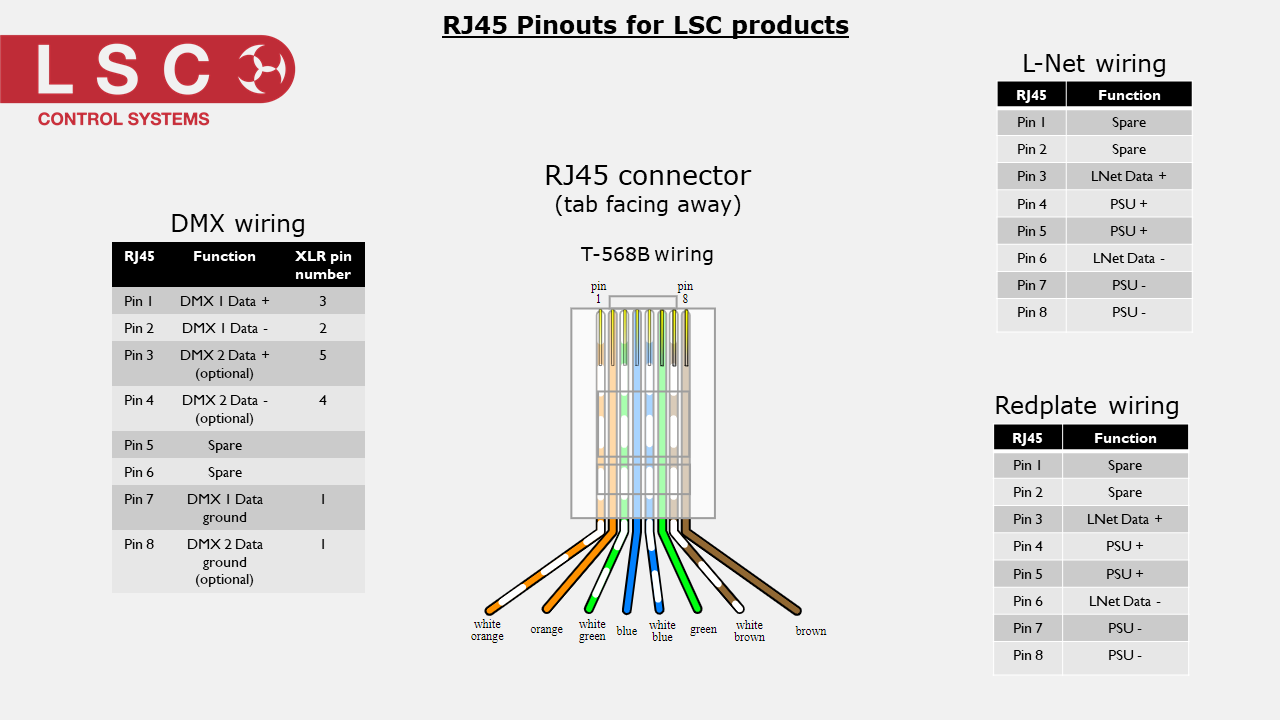
RJ45 pinouts for DMX, LNet and Redplates
(Right click on image and select 'Save Image As' to save the picture to your device).
